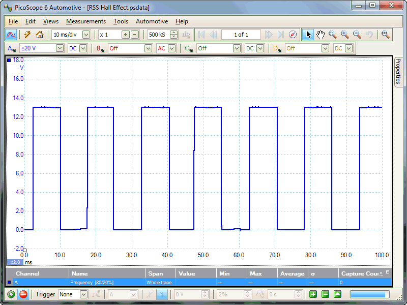
Hall effect sensor for cam speed sensor speed sensor Circuit Diagram However, for applications that involve high-speed detection, like in the case of speedometers, high-frequency Hall Effect sensors like US5881 or US1881 should be used. There are two main types of Hall Effect sensors: Latching Hall Effect sensors. Non-latching Hall Effect sensors. The US1881 is a latching Hall Effect sensor.
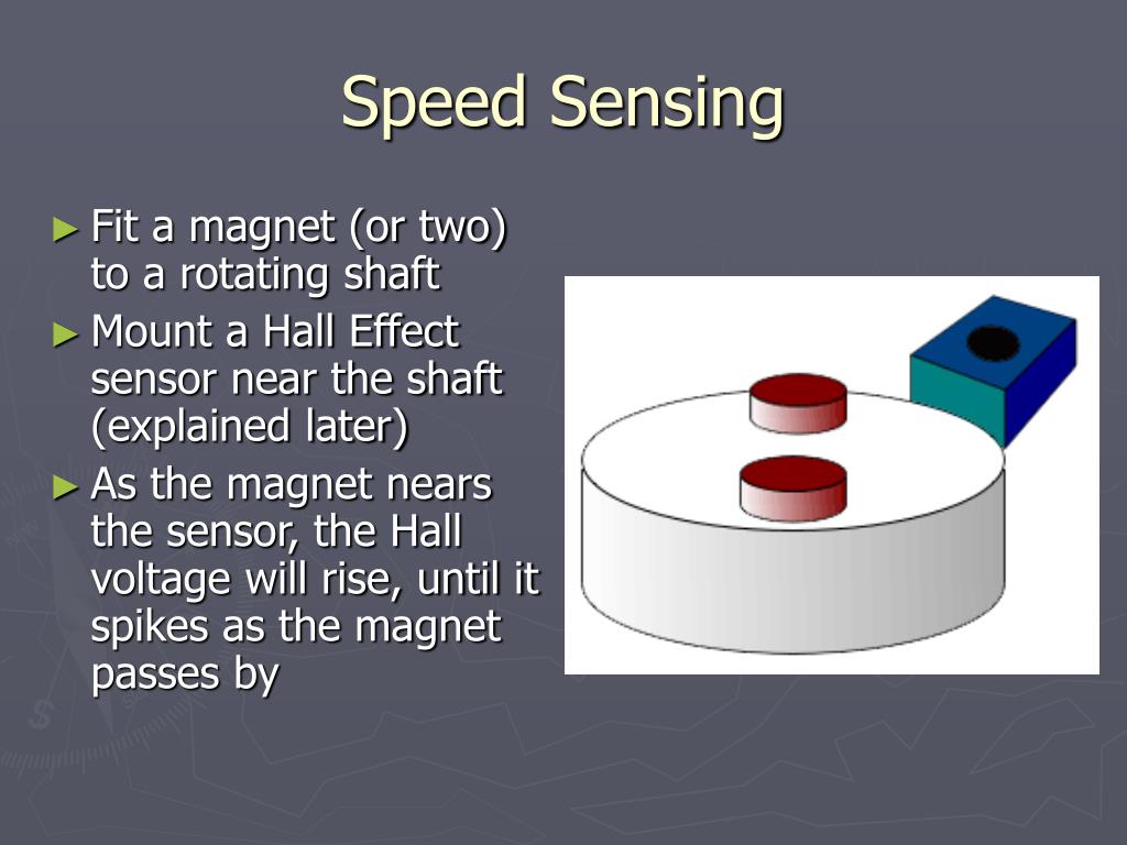
I'm using an ominpolar hall effect sensor from Allegro I think, I've used these in the past for another project and it seems to be working fine. It's reading the magnet, and I've done the basic sketch to illuminate the on board LED of the UNO. The screen is a basic 128 x 32 OLED thing, and again it's functioning well. A Hall-effect sensor varies its output voltage in response to a magnetic field. Hall-effect devices are used as proximity sensors and for positioning, speed, and current detection. They are widely used in motor control systems. A Hall-effect sensor is a long-lasting solution because there are no mechanical parts to wear down over time.
How to use Hall Effect Sensor with Arduino? Circuit Diagram
Proximity (distance) detection, power sensing, speed detection, and current sensing applications. For example time the speed of wheels and shafts, alarm systems, keyboard and printers. The advantages of using a Hall effect sensors are: • A "invisible" sensor. Non contact operation so there is no wear and friction.

Control a Relay with Arduino and Hall Effect Sensor. The circuit diagram for controlling a 5V Relay Module with Hall Effect Sensor and Arduino is shown below. Code. Working. The working of this circuit is very simple. Whenever the Hall Effect Sensor is subjected to a magnetic field, it toggles the Relay (as per the code). Applications of Hall As per the diagram we are connecting the positive terminal of the sensor to Pin 2 (5V) and the negative to Pin 6(Ground). The signal pin of the hall effect sensor is connected to Pin 8(BCM 14). Signal pin on the above linked hall effect sensor is marked with an "S" next to it.Here is a link to Raspberry Pi pin-out diagram for reference. Hello, hope you are well. I have a project in electronics in which I need to measure the rotational speed of a fan using a hall effect sensor and display this speed on a 16x2 lcd. I have no problem with the display on the LCD. But I don't know how to go about it with the hall effect sensor to be able to measure the rotational speed of a fan.
Motor Speed Control Using Hall Circuit Diagram
Hello, I am trying to measure the speed of a bicycle wheel using a hall effect sensor. I am using the code below and get the RPM which I then convert into m/s. However, I want the measurement to be more accurate. Using my code the RPM changes by 60 which is roughly 2 m/s. I want a more accurate speed measurements with not such big intervals
