Solved Objective Create lowpass filter circuits in Circuit Diagram To surmount this problem, active circuit designs were introduced. When a passive low pass filter is connected to an Op-Amp either in inverting or non-inverting condition, it gives an active low pass filter design. The connection of a simple RC circuit with a single Op-Amp is shown in the image below.. First Order Active Low Pass Filter with the frequency response This article explores the analysis and design of passive low-pass filters. These circuits play an important role in a wide variety of systems and applications. The RC Low-Pass Filter We can attempt to create a second-order RC low-pass filter by designing a first-order filter according to the desired cutoff frequency and then connecting two

Just want some suggestion design low pass filter circuit for my 40w-4ohms speaker as my subwoofer, thanks. Posted on September 09th 2022 | 10:00 pm. Reply. Karthick R. Can remove low and high pass filter from amp board. Posted on August 31st 2022 | 10:33 am. Reply. John.
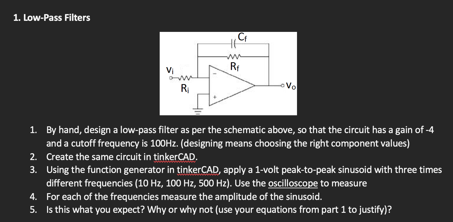
Active Low Pass Filter: Design and Applications Circuit Diagram
Active Low-Pass Filter Design Jim Karki AAP Precision Analog ABSTRACT This report focuses on active low-pass filter design using operational amplifiers. Low-pass filters are commonly used to implement anti-aliasing filters in data acquisition systems. Design of second-order filters is the main topic of consideration.
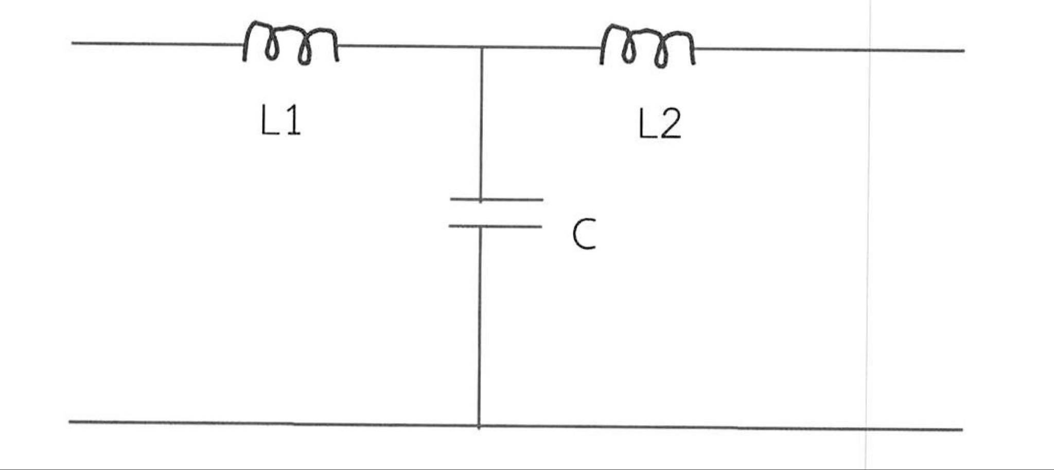
The formula and schematic for the LC low pass filter: Let's analyze a low pass filter with a practical example : Q. Design a low pass filter having cutoff frequency 'fc' = 75MHz and Vin = 5 volts using RC filter? Solution: given -> f = 75Mhz. R = 100 Ω(assumed)——-
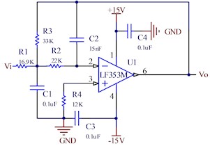
Active Low Pass Filter Circuit Diagram
The following images depict the standard opamp based low pass filter circuits. The first one needs to be powered by a dual supply, and the second one works using a single supply voltage. Designing a Customized Low Pass Filter Circuit Active Low Pass Filter Example No1. Design a non-inverting active low pass filter circuit that has a gain of ten at low frequencies, a high frequency cut-off or corner frequency of 159Hz and an input impedance of 10KΩ. The voltage gain of a non-inverting operational amplifier is given as: